Establish a shared, solution-independent vocabulary for the Lunar Lander by identifying the core domain concepts before introducing requirements, behavior, or architecture.
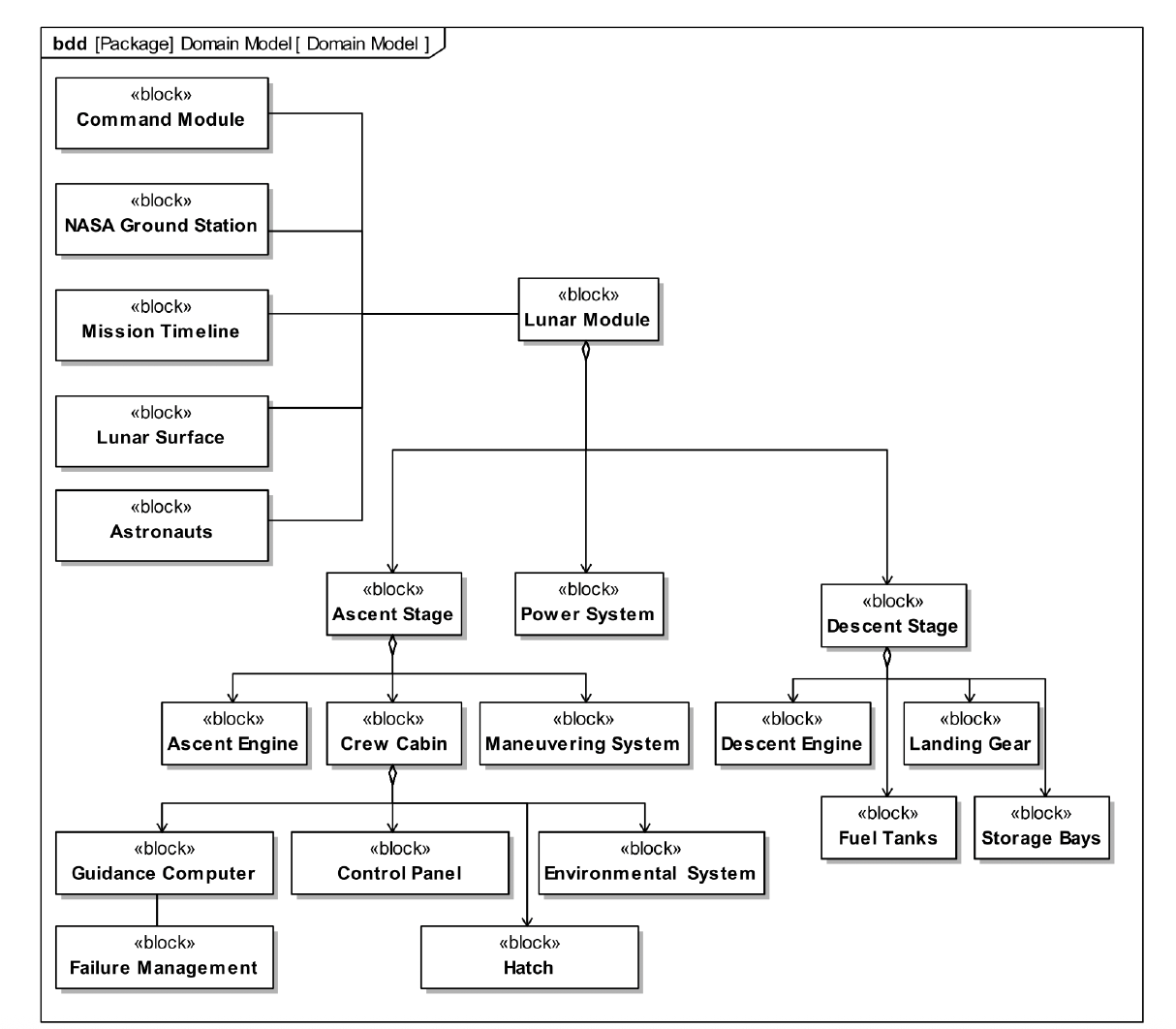
Identify the core domain concepts for the Lunar Lander problem domain. The domain model is not restricted to Lunar Lander internals and may include external entities such as the Command Module, Mission Control, crew, and the lunar environment. This is a problem-domain model, not a decomposition of the Lunar Lander.
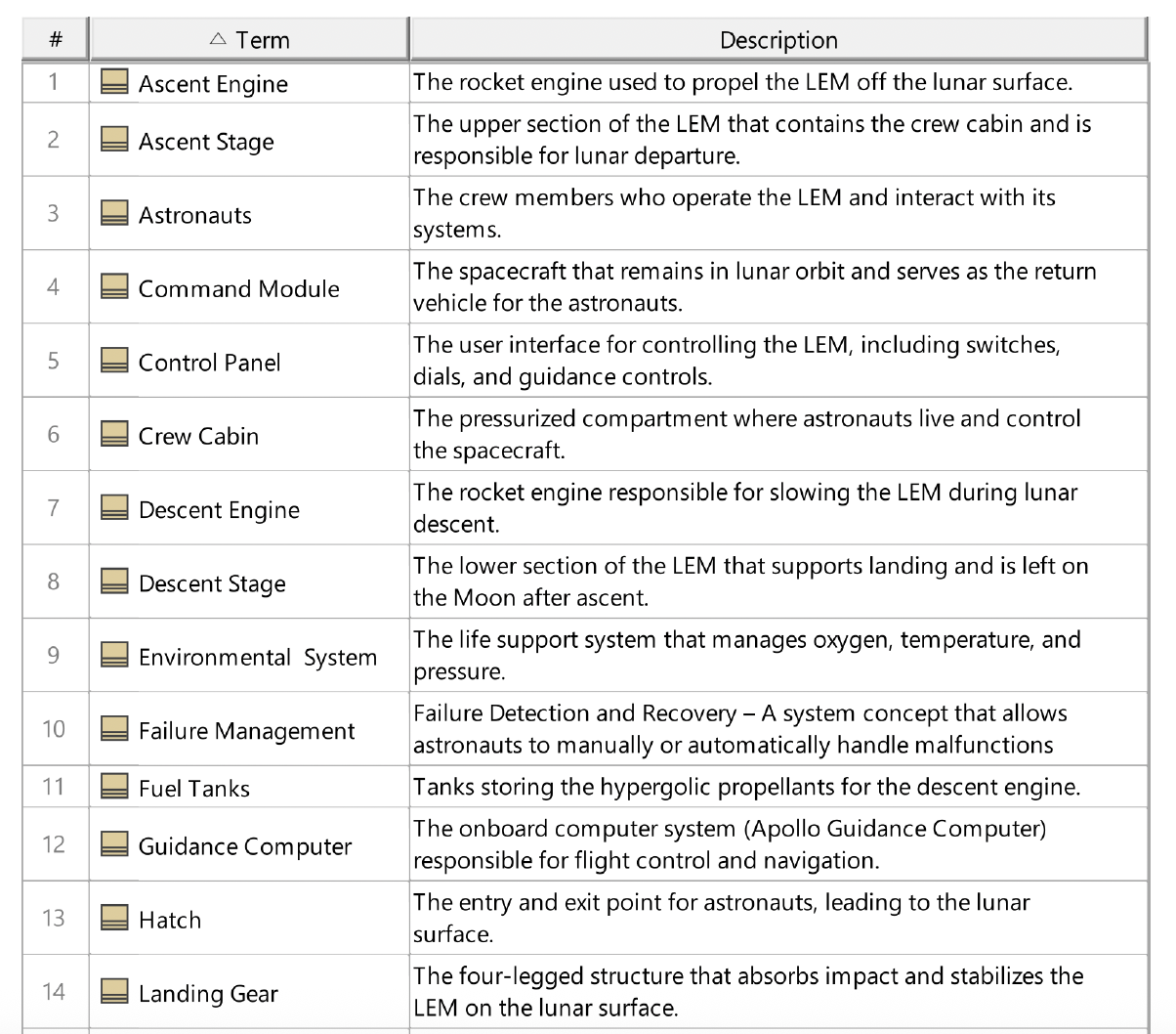
Create a new glossary table diagram. In the containment tree, locate the Domain Model package, select all domain blocks, and drop them onto a glossary table. Then write concise definitions for each term.
Organize requirements into explicit categories in order to reduce omissions and improve clarity. This lab focuses on capturing different classes of requirements one category at a time.
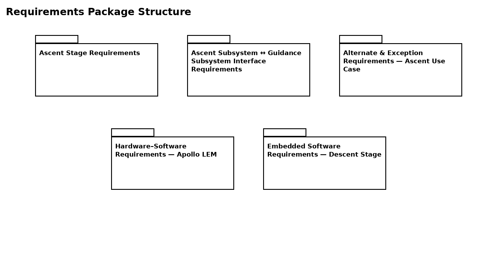
Create a package diagram with one package per requirement category. Use file-folder style packages whose names correspond to the requirement tables provided.
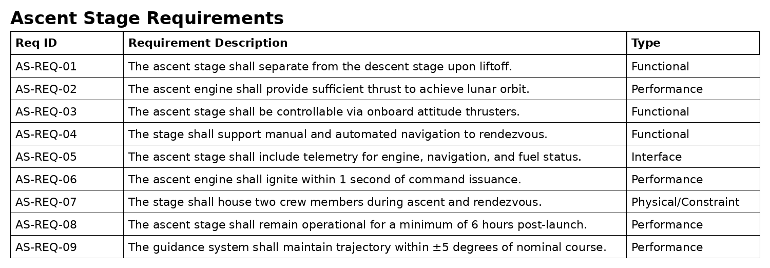
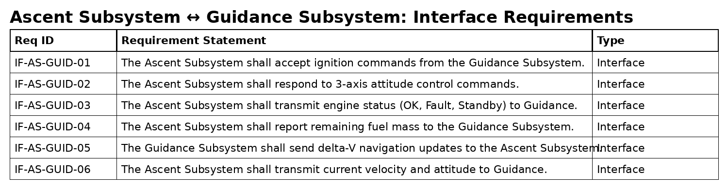
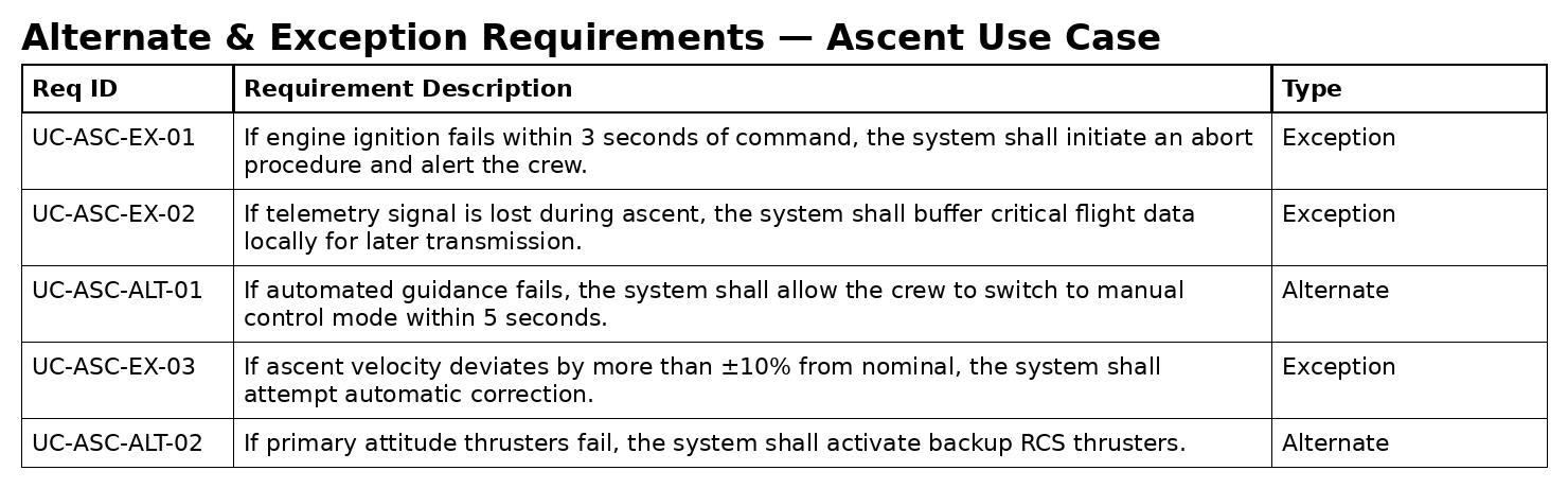
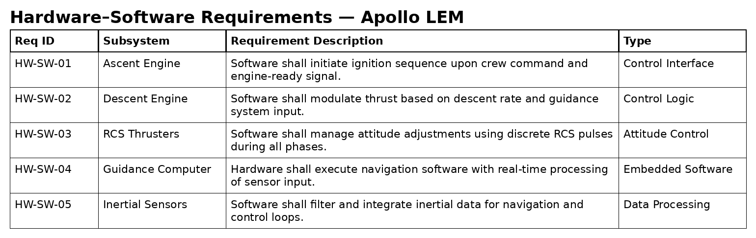
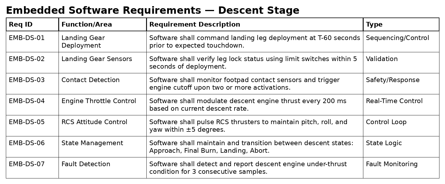
Inside each package, capture the requirements using either requirements tables or requirements diagrams. For each requirement, write the requirement text as a shall statement.
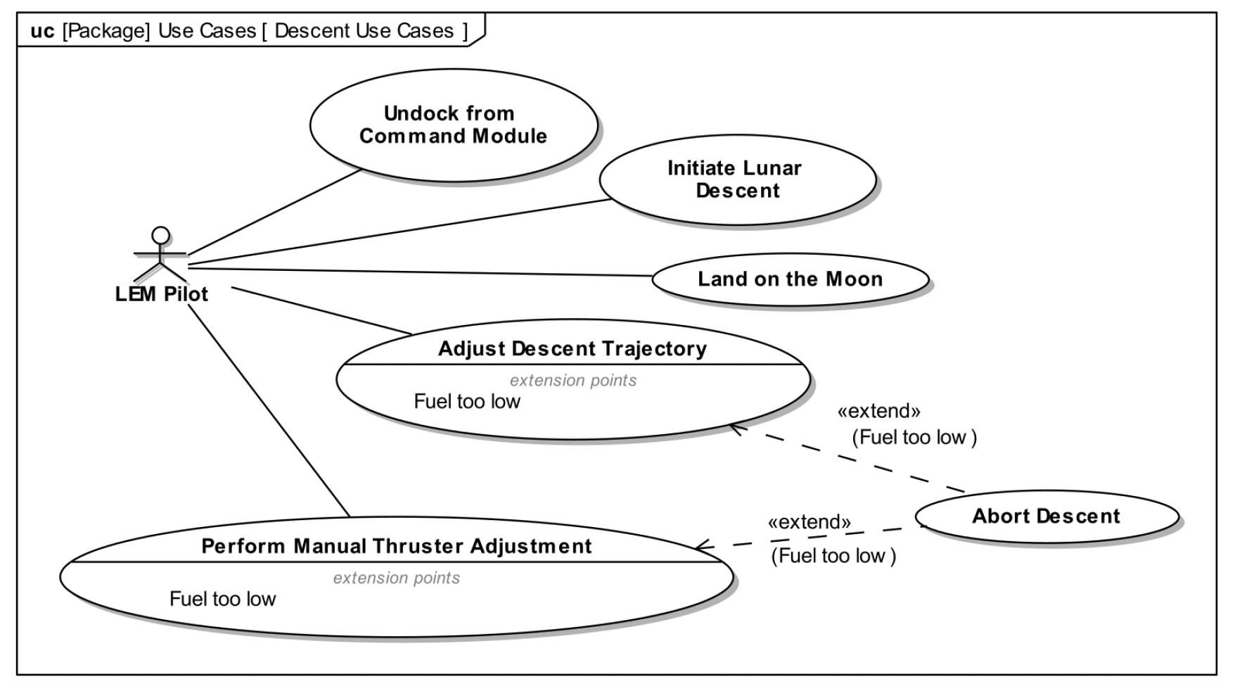
This lab introduces use case modeling using two core Lunar Lander scenarios. Students will first recreate the ascent and descent use case diagrams, then write a compact use case narrative using a standard template.
Create the following two use case diagrams. Use them as references and recreate them in your model.
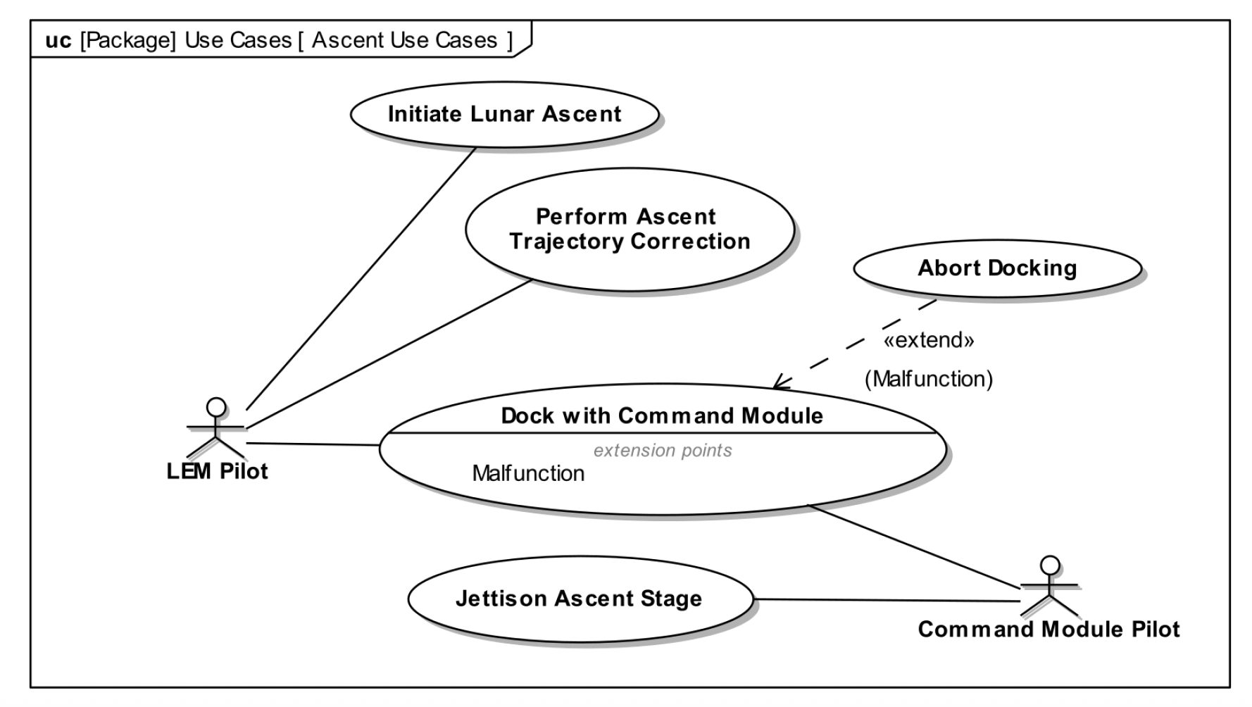
Write the use case narrative for the use case: Dock with Command Module Use the following format.
Use Case: Dock with Command Module Primary Actor: LEM Pilot Supporting Actor: Command Module Pilot Basic Path: 1. LEM Pilot initiates docking maneuver. 2. Guidance system provides relative position and velocity. 3. Pilot aligns docking interface. 4. Docking mechanism engages and locks. 5. System confirms successful dock. Alternate Path (Malfunction): 3A. Docking mechanism fails to engage. 3A1. Abort Docking is initiated. 3A2. LEM retreats to safe distance.
1. In your model, create a new package called Logical Architecture. 2. Inside this package, create a new Block Definition Diagram (BDD) also called Logical Architecture.
1. Review your domain model from Lab 1. 2. Look for domain objects that hide a lot of internal complexity (for example, Telemetry may hide antennas, amplifiers, encoder/decoder, etc.). 3. For each such object, create a corresponding subsystem block on the Logical Architecture BDD (for example, from Telemetry create Telemetry Subsystem). 4. Note that any domain objects that are not part of the Lunar Lander are definitely not subsystems (for example, Mission Control, Command Module, Lunar Surface).
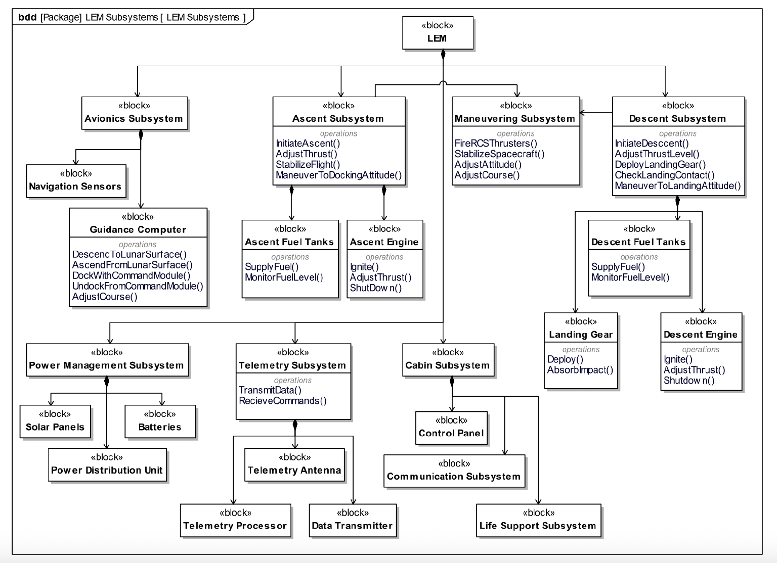
1. On the Logical Architecture BDD, add a top-level block called Lunar Lander (if it does not already exist). 2. Use composition relationships to connect Lunar Lander to each subsystem block you identified in Part 2, as shown in the example diagram below. 3. (Optional) For some of your subsystem blocks, add actions or operations that represent key behaviors.
In the Logical Architecture model, find the Telemetry Subsystem block and create a new state machine diagram owned by this block. Name it Telemetry Controller.
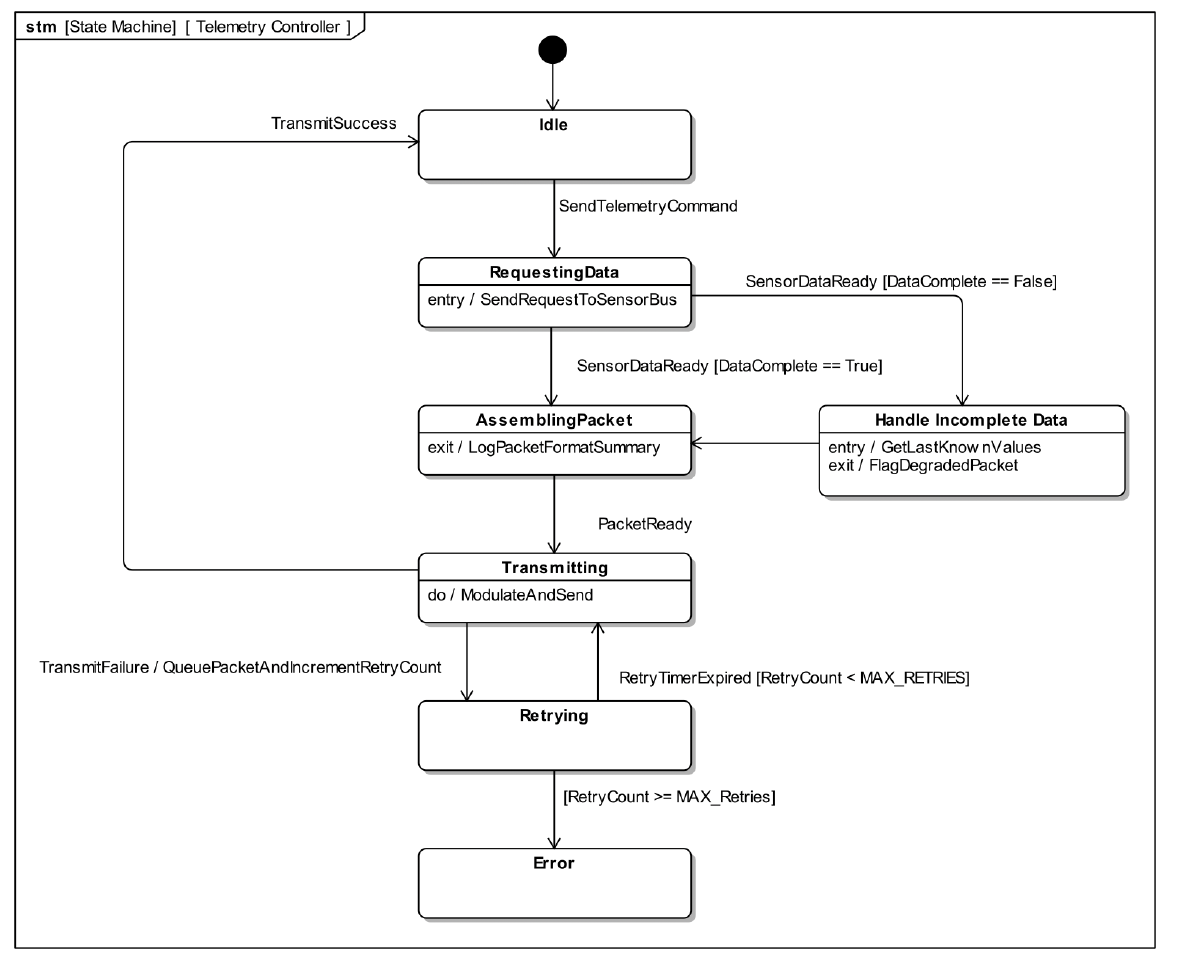
Using the Telemetry Controller example diagram, add the same states and transitions so your state machine has the same overall control flow.
Add entry, do, or exit behaviors to some of your states following the example diagram.
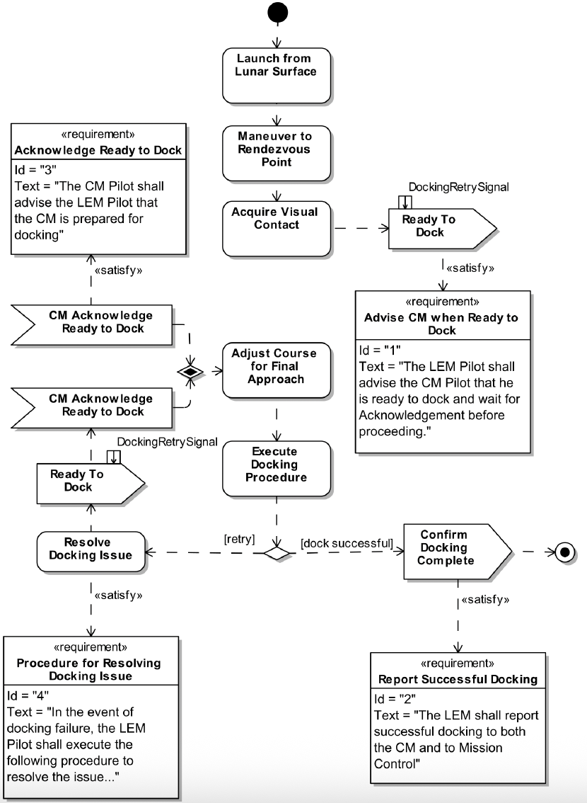
1. In your model, find the use case Dock with Command Module and create a new activity diagram under that use case named Dock with Command Module. 2. Add the actions and control flows for the docking scenario so that the diagram shows the basic control logic from launch through confirm docking complete. 3. (Optional) Add the requirements overlays (for example, advise ready to dock, acknowledge ready to dock, resolve docking issue, report successful docking) using requirement elements and «satisfy» relationships, as shown in the example diagram below.
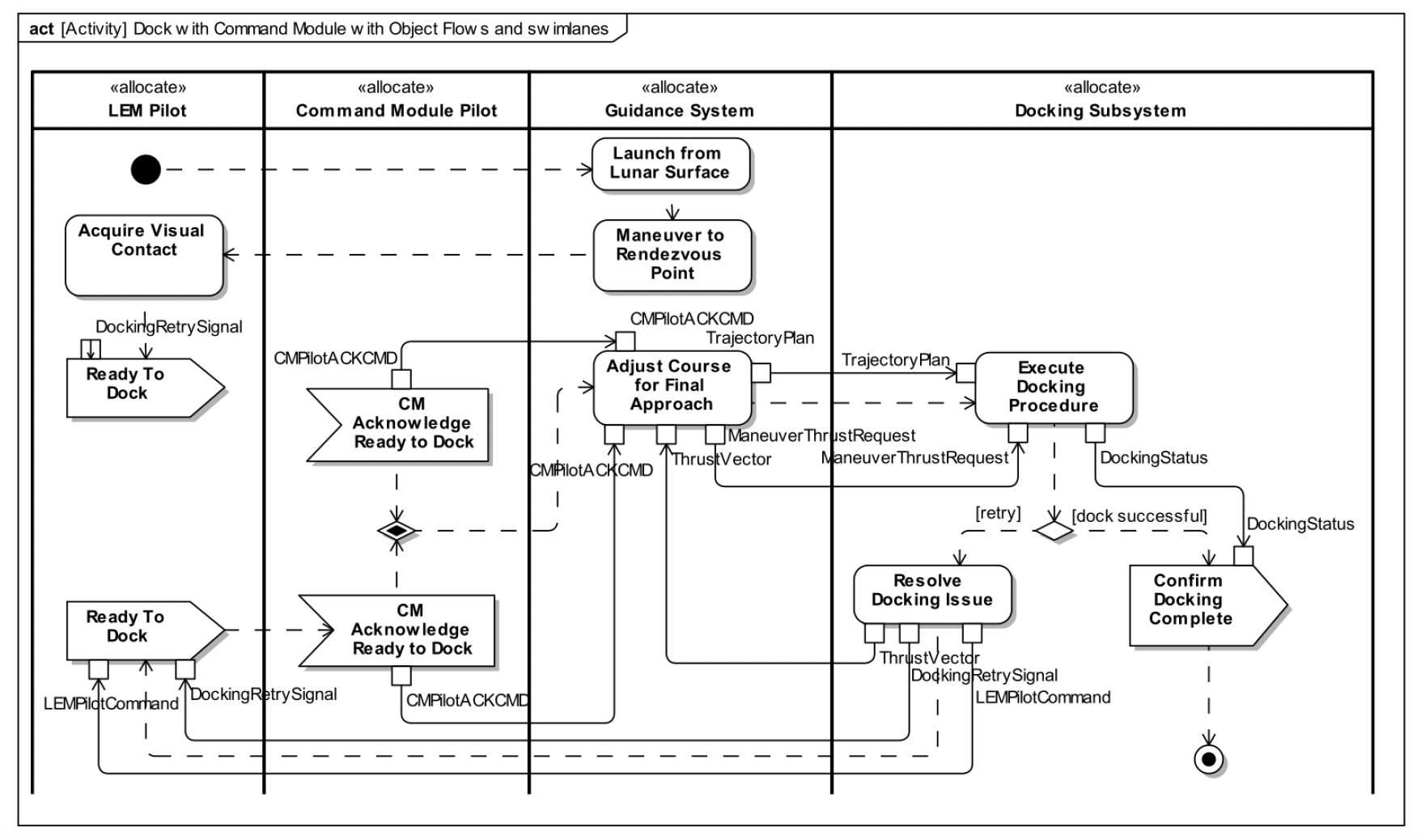
Starting from your Part 1 activity diagram, add input/output pins and activity parameters, object flows, and swimlanes to show how responsibilities and data are allocated, following the example diagram below.
Find the Send Telemetry use case and create a sequence diagram under it named Send Telemetry.
In the Logical Architecture package, identify the blocks that participate in this use case and drag them onto the sequence diagram to create lifelines. If required lifelines are missing, update your Logical Architecture first, then drag any new blocks onto the sequence diagram.
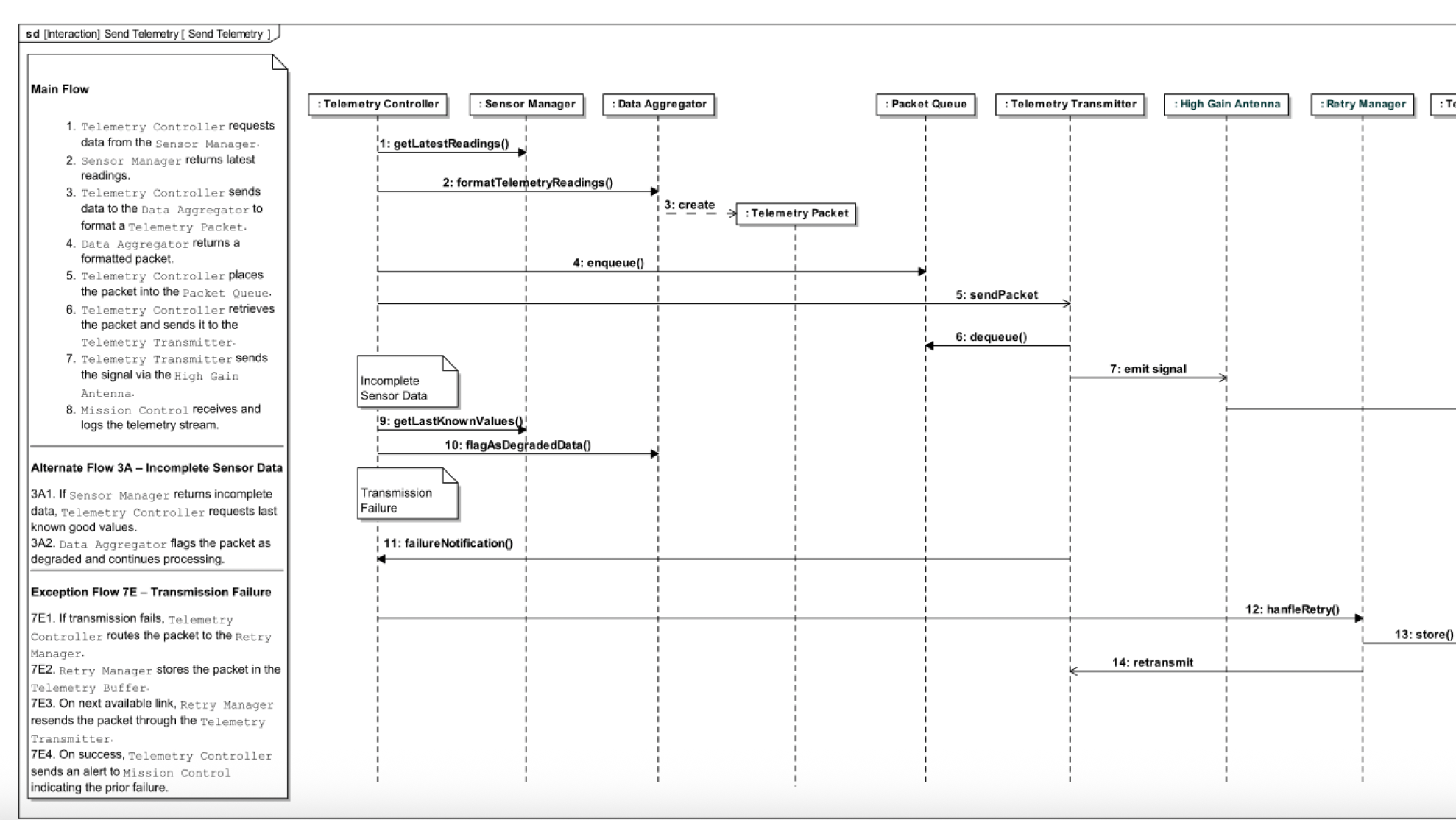
Example sequence diagram (Send Telemetry):
Using the use case narrative as a guide, add messages between lifelines to allocate responsibility across subsystems.
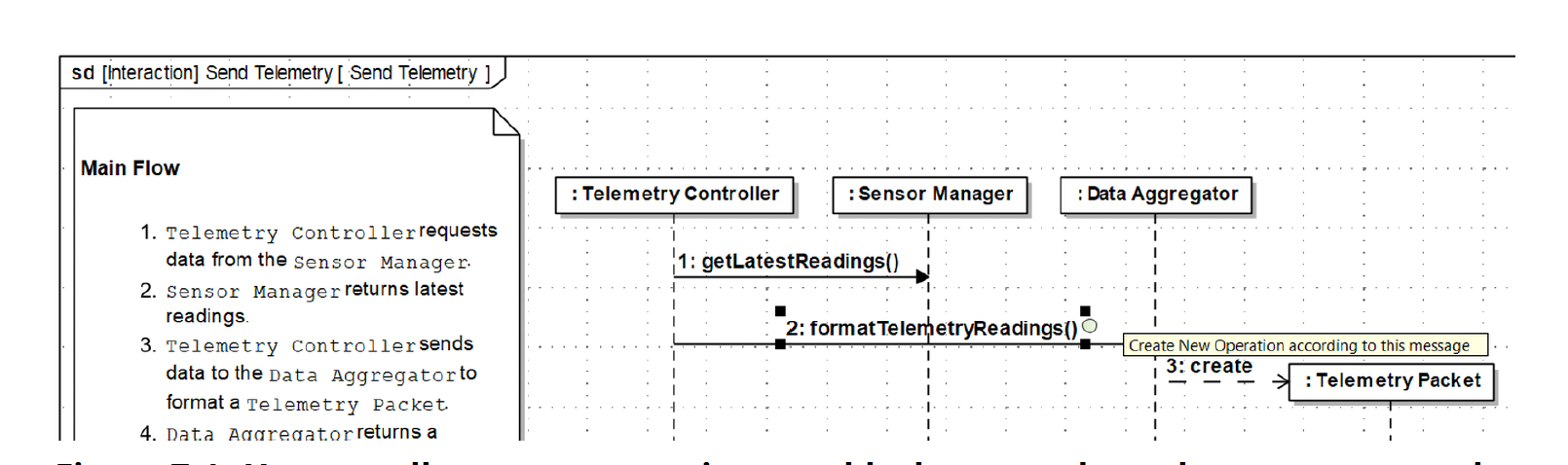
As each message is created, right-click on the message and add it as an operation on the target block. After allocating messages, review your Logical Architecture diagram and confirm that the operations appear on the blocks you expect.
Example: creating an operation from a message:
Add a note in the margin and display the use case narrative directly on the sequence diagram.
Add operation signatures to messages (for example, sendPacket(packet: TelemetryPacket)). This process replaces using activity parameters and pins on activity diagrams with a stronger and more meaningful treatment of data flow.
Add additional refinements as desired (alternate or exception flows, return messages, interaction fragments, sync vs async).
In this lab you will create an internal block diagram (IBD) for the LEM using interface blocks and proxy ports to model how the top-level subsystems are connected.
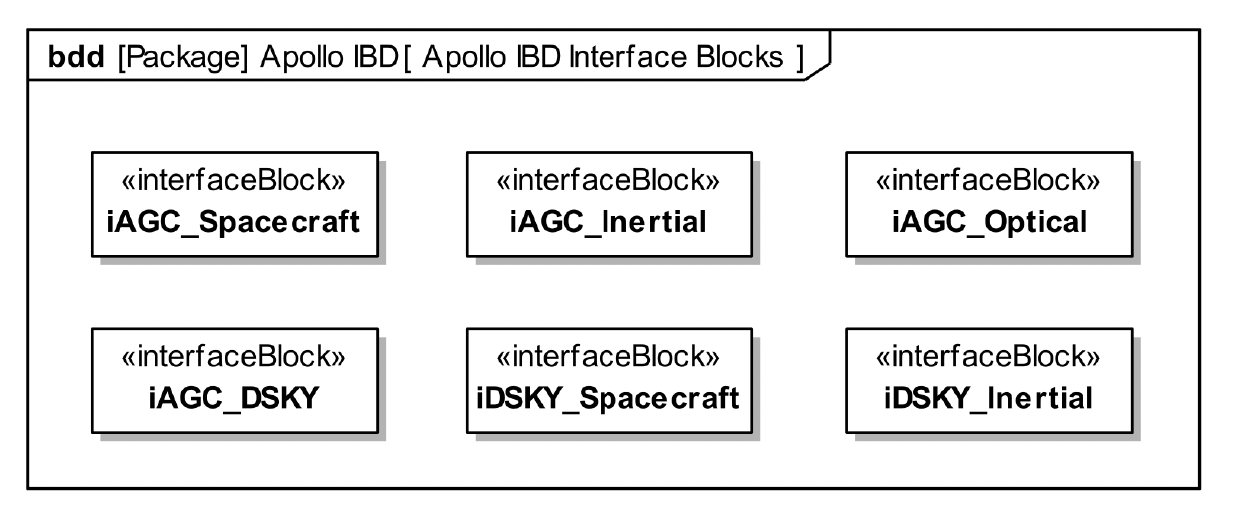
In a new package (for example, Apollo IBD), create interface blocks for each connection between the LEM subsystems (AGC, DSKY, Spacecraft Bus, Inertial Subsystem, Optical Subsystem). Name and organize them as shown in the Apollo IBD Interface Blocks diagram.
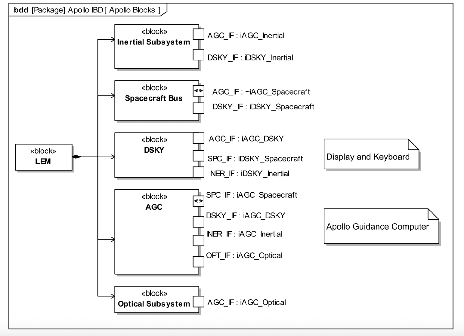
On the Apollo Blocks BDD containing LEM, AGC, DSKY, Spacecraft Bus, Inertial Subsystem, and Optical Subsystem, add proxy ports to each subsystem block and type those ports with the interface blocks from Part 1. Arrange the ports and their names around the blocks so the interfaces are readable, as in the example diagram.
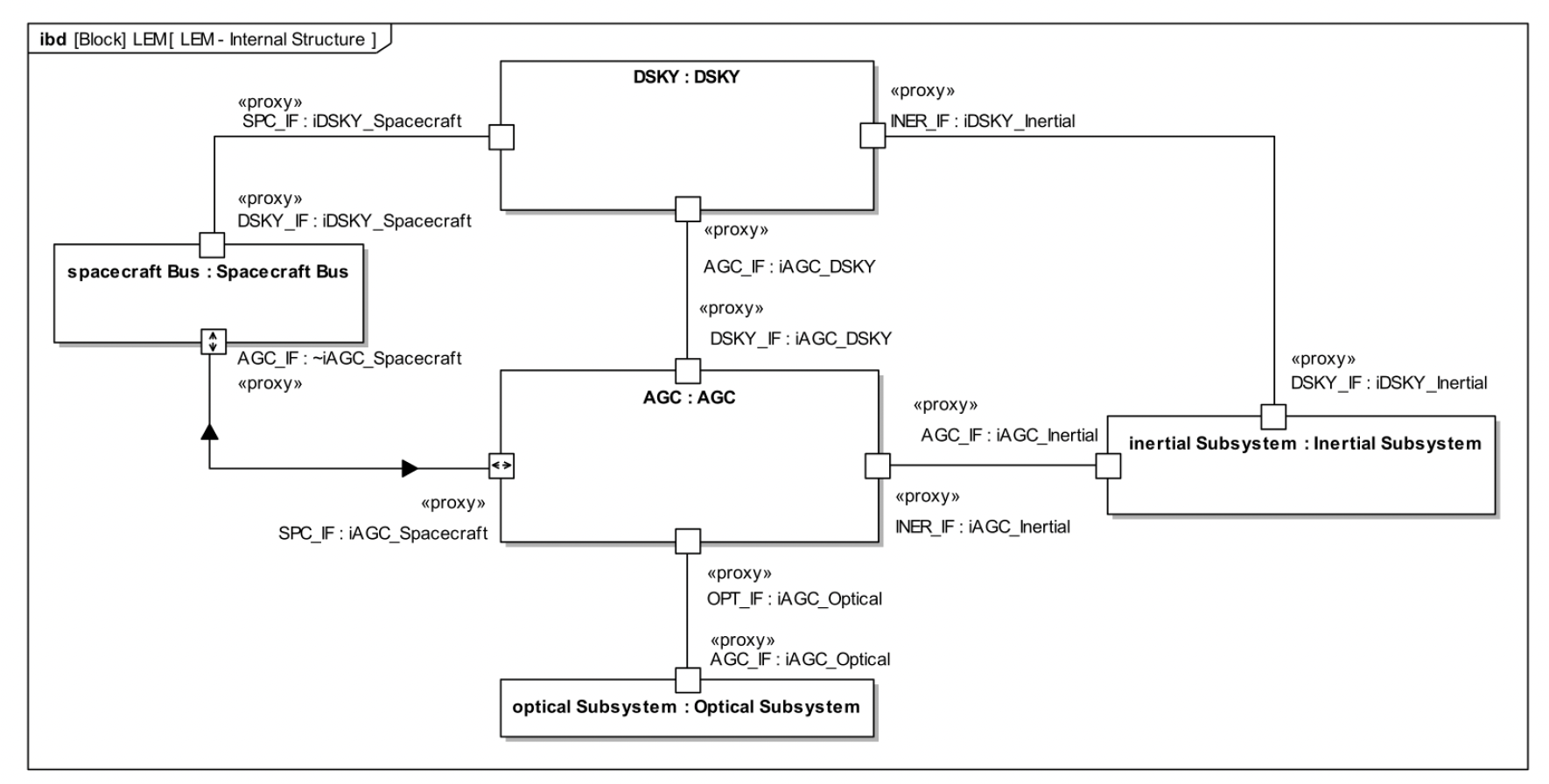
Create a new internal block diagram owned by the LEM block (for example, LEM – Internal Structure).
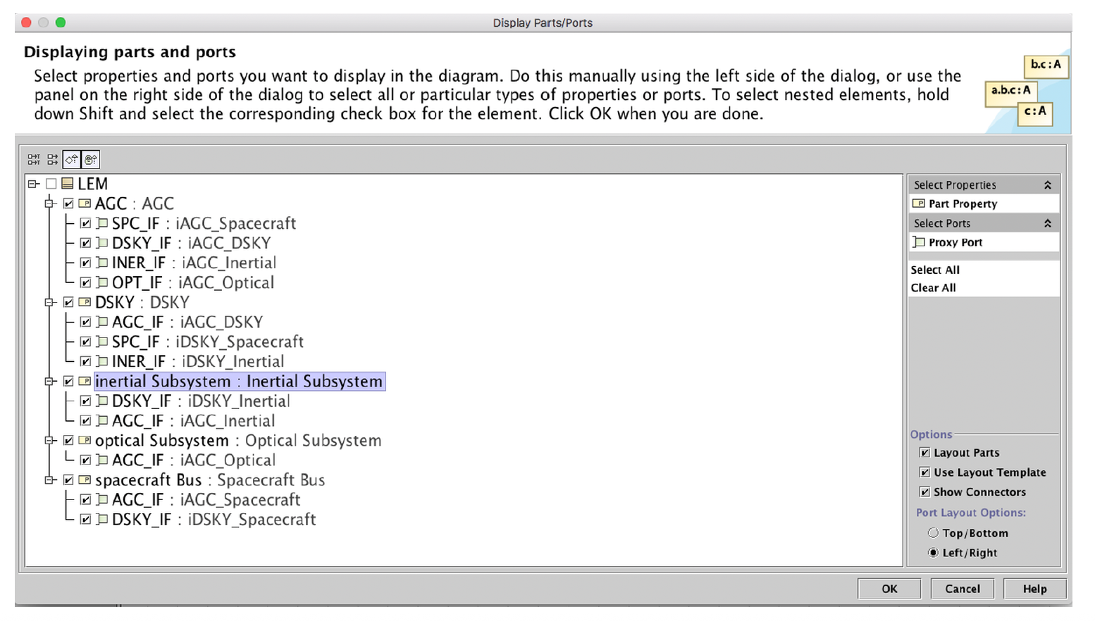
Use the Display Parts/Ports dialog to automatically show part properties for the top-level subsystems (AGC, DSKY, Spacecraft Bus, Inertial Subsystem, Optical Subsystem) and their ports typed by the interface blocks you created.
On the IBD, connect matching ports with connectors so that every interface block you defined is realized by at least one connector between the appropriate subsystems, as shown in the completed LEM internal block diagram.
In this lab you will define constraint blocks for Lunar Lander descent kinetics and create a simulation context diagram that will be used for parametric analysis.
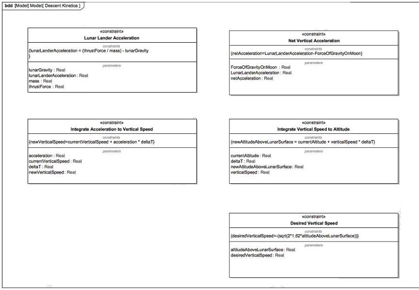
In a new package (for example, Descent Kinetics), create the set of constraint blocks shown in the Descent Kinetics constraint-block diagram. Note: this lab only uses the Lunar Lander Acceleration constraint block, so you can safely skip the others.
For each constraint block, add the parameters and constraint expression so that your BDD matches the example diagram (names, types, and formulas).
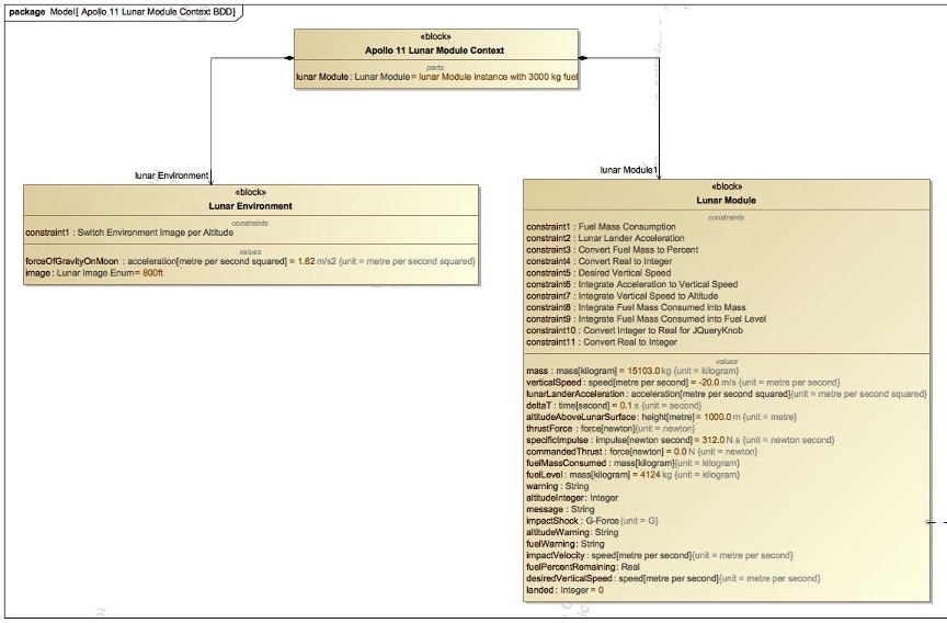
Create a BDD named Apollo 11 Lunar Module Context and reproduce the structure shown in the Lunar Module context diagram: Apollo 11 Lunar Module Context, Lunar Module, and Lunar Environment, with the appropriate part and association relationships.
On Lunar Module and Lunar Environment, add constraint properties and value properties so that your context diagram matches the example (including initial values).
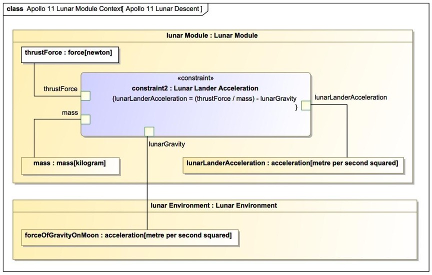
In this part you will create a parametric diagram that binds Lunar Module and Lunar Environment value properties to the parameters of the Lunar Lander Acceleration constraint block. 1. Under the Apollo 11 Lunar Module Context package, create a parametric diagram. 2. Add the Lunar Lander Acceleration constraint property to the diagram. 3. Bind the value properties to the constraint parameters as shown in the diagram 4. Verify that all constraint parameters are bound and that the parametric diagram is fully connected, with no unbound pins. This parametric will be reused directly in Lab 10 to drive the time‑based descent simulation.
This lab builds a minimal, time-based simulation of a lunar module descent. The intent is to understand how gravity and commanded thrust affect altitude and vertical speed over time, without introducing propulsion physics. A more complete reference model is provided separately.
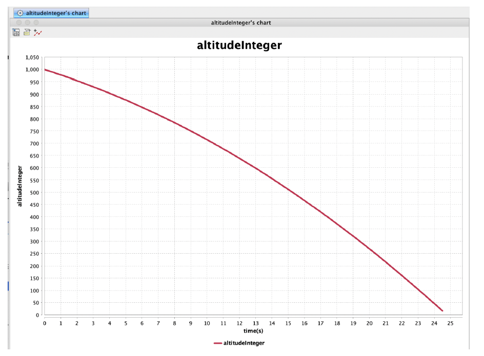
Using the constraint blocks defined in Lab 9, simulate a gravity-only descent. No thrust is applied in this phase. Plot altitude versus time to establish a baseline.
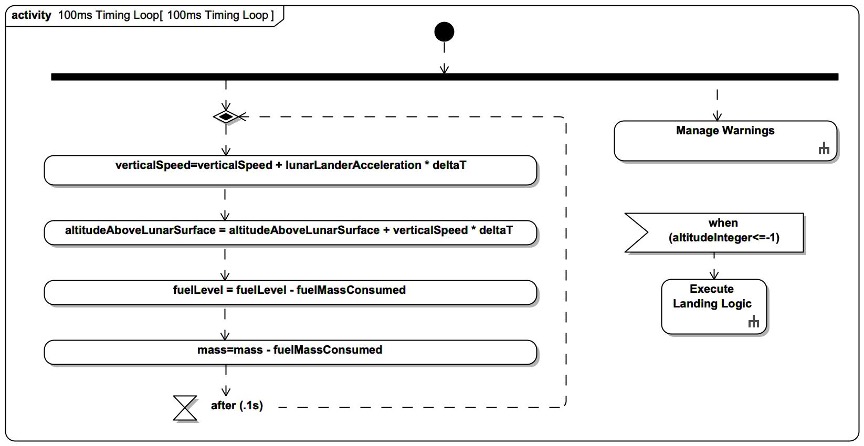
Create a 100-millisecond timing loop using opaque actions. Opaque actions are required for executable simulation. Call behavior actions may be used for higher-level logic such as warnings or touchdown detection.
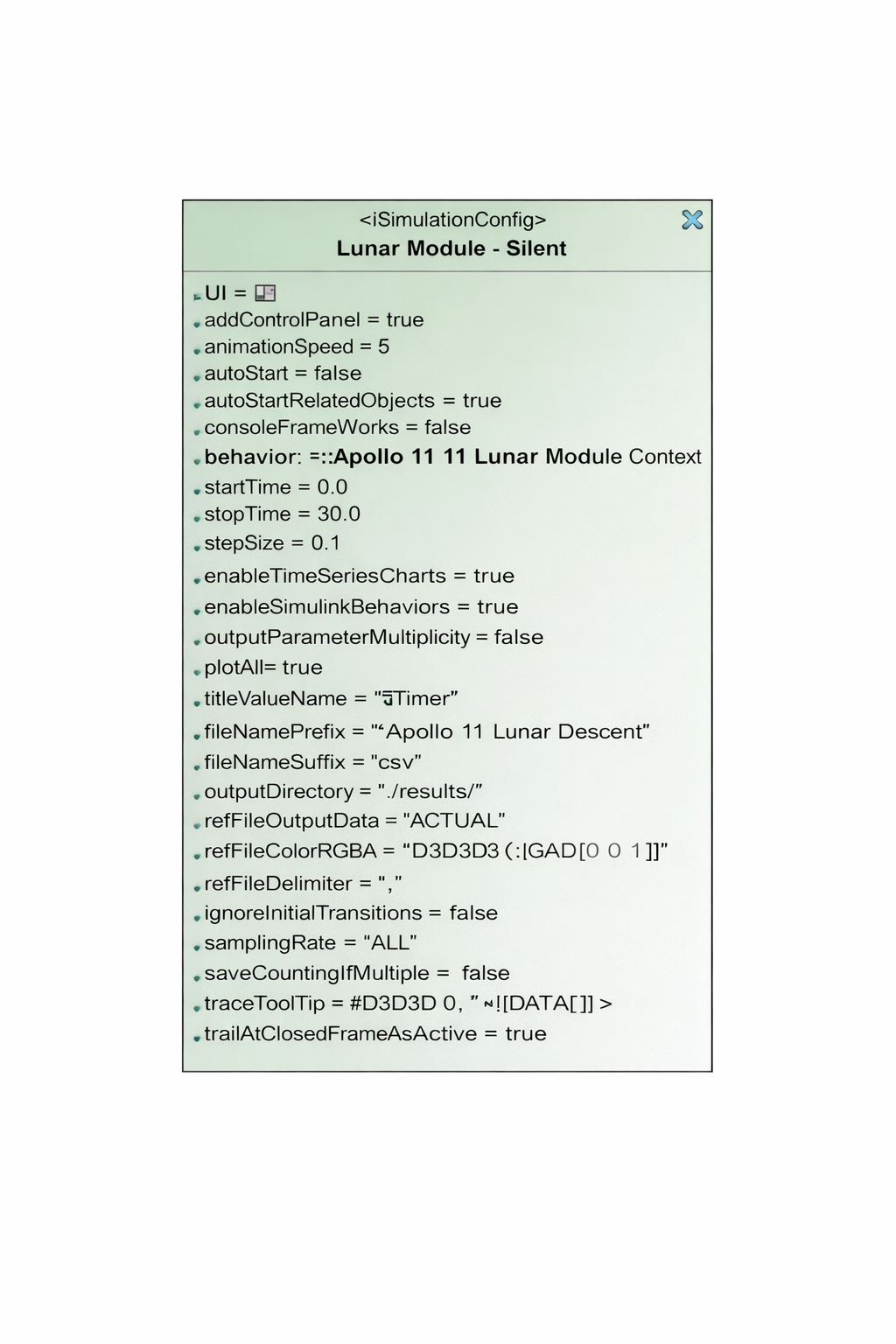
Create a simulation configuration with the following settings: • Start time = 0 • Step size = 0.1 seconds • No stop time • Execution target set to the appropriate simulation context
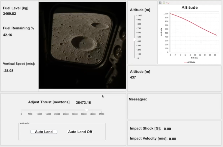
Create a user interface diagram to observe and control the simulation.
Create a new User Interface Diagram in the containment tree under the simulation context. Add frames, charts, sliders, and other UI elements as needed. UI elements are bound directly to model elements selected from the containment tree.
Bind a slider on the user interface diagram directly to the thrust value property of the Lunar Module block. Set the slider limits from 0 to 45,000 newtons. This thrust value is applied directly in the descent acceleration computation.
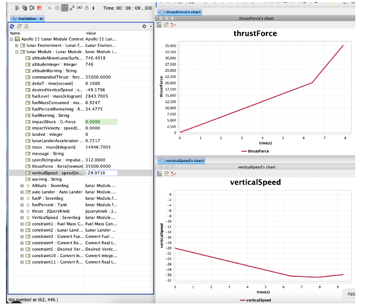
Run the simulation with thrust enabled and observe the effect on vertical speed. Plot thrust versus vertical speed to see how commanded thrust counters gravity.
Optional next step (only for the brave): extend the model to account for fuel mass decreasing as thrust is applied.